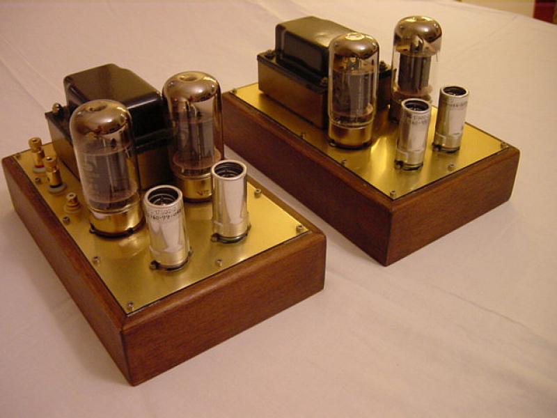
SET direct heated triode tube power amp
Direct heated triode power output tubes are really interesting. Since September 2008 I've been working in a new project regarding a single ended triode tube power amp using the 811A vacuum tube. Actually it is a project with a long process of experimentation.
The 811A vacuum tube it is a power triode capable to output 10 - 15 Watts in a single ended class A2 configuration, in a three stages circuit using interstage transformer in the driving stage.
It's all about a double project. At first I built a prototype amp using the SV811-3 tube. Afterwards I built another one using the 811A tube.
![diy-811A-amp-details]()
watch the video : Testing the prototype audio amp SV811-3
Nobu Shishido was one of the first engineers who introduced a design like this. His designs are showcased by the well known WAVAC Audio Labs.My project is based on the Shishido's 811A design as well, but with several changes in his circuit.
Input stage and driver stage
In Shishido's design the input stage consists of an ECC82/12AU7 dual triode connected as a series cascode mu-follower circuit . The signal from the mu-follower stage is directly coupled to the grid of a 6F6 power tube connected in triode , with no use of a coupling capacitor in the signal path.
Instead of using a cascode circuit, I decided to use the EF86 tube ( triode strapped ) for the input stage of the amplifier to provide high-gain voltage amplification. The credit for this choice ( EF86 ) goes to Mr Giannis Spathopoulos. The input stage is coupled directly to the grid of a 6L6GC tube with no coupling capacitor in the signal path. The purpose of this is to minimize low-frequency phase shift in the amplifier and to improve the low-frequency stability when negative feedback is applied.
For the SV811-3 typical operation ( for plate Voltage = 450 to 500 Volts) is A2. Class A2 means that the grid is driven more positive than the cathode for a part or all of the waveform. For the first 5 Watts, operation is A1 and from 5 watts to the max power A2. Grid voltage is about 40 Volts at max power, and this is because grid will draw current from the cathode and heat up. Class A2 also requires a beam power tube in the driver stage , that can supply enough power to the grid.
Driver stage consists of a 6L6GC tube connected in triode running at 260 Volts. The interstage transformer is a C core type transformer, 1:1 5K primary impedance ( equivalent to TANGO NC-20F ). The output stage ( 811A tube ) operates in class A2. Plate voltage is 450 Volts and plate current 75mA when no signal applied.
The new 811A DHT single ended amp :
![811A-left]()
The SV811-3 prototype :
![diy-tube-amps-sv811-3-prototype]()
The Interstage transformer coupling method :
There are three common coupling methods :
a. Capacitor coupling
b. Direct coupling and
c. Interstage transformer coupling.
For the first option, coupling capacitor works allowing only AC signal (audio frequency ) to pass. The major problem is the quality of the coupling capacitor and its characteristic contributing to the audio signal (different sonic and tonal characteristics of the capacitor - even thought using the same brand - of capacitors ).
On the other hand the direct coupling designs allow both DC and AC signals pass to the grid of next gain stage. This seems to be good but the subsonic oscillations (hum and RF) sometimes pass through the final gain stage producing noise and a kind of blear and harsh sound.Another problem is that you have to work with exactly the same parameters in both channels ( matched pairs of driving and output tubes , accurate and exactly the same bias adjustment etc)
In my opinion the use of an interstage transformer is the best coupling method.
This is because the primary and secondary winding of the IT working almost the same. This leads to no loss of the magnetic energy converted into audio signal. Even thought it is the most expensive coupling method the use of an IT is the best coupling mechanism for tube audio amps.
The use of a quality IT is the secret key for high quality sound in Direct Heated Triode designs. ( e.g. WAVAC )
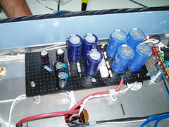
Underneath the prototype amp :
![diy-tube-amp-811-pcb]()
Underneath the new 811A amp :
![final-811A]()
Output and IT transformers
Except the power transformer , the IT and the OPT (output transformers) ( in all my projects ) are hand made designs made in a laboratory in Beograd (Serbia). Both OPT and IT are special orders according my needs and follow exactly the tube characteristics for each design. They are more expensive than ready made transformers but I know the quality of materials used is excellent.
Negative feedback
Currently No feedback is applied in both projects.
Negative feedback is taken from the secondary winding of the output transformer to the cathode circuit of the input stage (EF86). At the moment there is no feedback applied in the prototype amp. I think the amount of the feedback, could be 5-7dB in order to increase the damping factor, but it seems it is not necessary to apply feedback since we use sensitive speakers .
Power supply
The prototype amp uses an E-shape power transformer covered by the black box at the back. The metal cylinders with bolts are the capacitors ( 2 X 22000uF/16V /channel ) providing filtering for the filament DC circuit. Note that 811A cathode and filaments are together so we need a very careful design to avoiding hum .
In the new amp I m using a toroidal power transformer ( better quality than the E-shape transformer ) and bigger capacitors ( 2 X 33000uF/16V / channel ) for the filaments
The chassis for the 811A valve amplifier
New chassis are constructed from stainless steel 1.5mm thick. The cutting process was done by laser cutting machine. The chassis designed on the computer, and a fellow who has a laser cutting machine did the cutting and bending work.
Laser cutting is ideal because the results are so precise - edges are burr free with minimal gaps and also the rigidity of the base material (stainless steel sheet ) has no impact of the cutting process.
Both sides (left and right) coated by 10mm thick black acrylic.
The new chassis ( for the 811A ) :
![811A-chassis-1]()
The 811A project is already finished. I sent the 811A monoblocks to my friend Scott in Canada.
Here are some photos taken while assembling the 811A amp:
![811A-cover-open]()
![power-supply-811A-detail]()
![heaters-811A-detail]()
![power-supply-811A]()
![parts-811A-1]()
![assembling-811A-2]()
costas sarris
The draft schematic of my 811A single ended tube power amp ( positive grid bias ) class A2:
![SE-811A-schematic]()
The PSU
![PSU-811A-schematic]()
The modified schematic using the Svetlana SV811-3 (negative grid bias ) class A2
![SE-SV811-3-schematic]()
The hand made interstage transformers
![interstage-81A]()
![se811A-6]()
The prototype amp ( with the SV811-3 ):
![tube-amp-SV811-3-prototype]()